Thermal Evaporators Processes
ENCON Thermal Evaporators - How Do They Work?
Evaporation and Distillation Mode
- Wastewater is collected in a holding tank, sump, or pit and is either pumped or gravity fed into the wastewater evaporator through a 1" NPT fitting on the lid.
- The three (3) level probes in the standard auto-fill system provide:
- Low Level (LL) provides on/off control for the heat source.
- Auto Level (AL), along with timer based control function from the PLC, initiates and stops the fill sequence.
- High Level (HL) is a redundant safety for the auto level (AL).
- As the fluid flows into the wastewater evaporator and reaches the low-low level probe, the heat source will activate (see respective heat source diagram).
- Fluid will continue to flow until it reaches the high-auto level probe. At this point, the feed sequence will stop.
- As the fluid comes to a boil and the evaporation process begins, the liquid level will drop down to the low-auto level probe. The feed sequence will activate and more fluid will be fed into the wastewater evaporator until the level reaches the high-auto level probe.
- The wastewater evaporator system will continue to cycle in this manner until either the fluid temperature controller reaches the high set point, the cycle timer counts down to zero, or there is no longer wastewater to be fed to the evaporator.
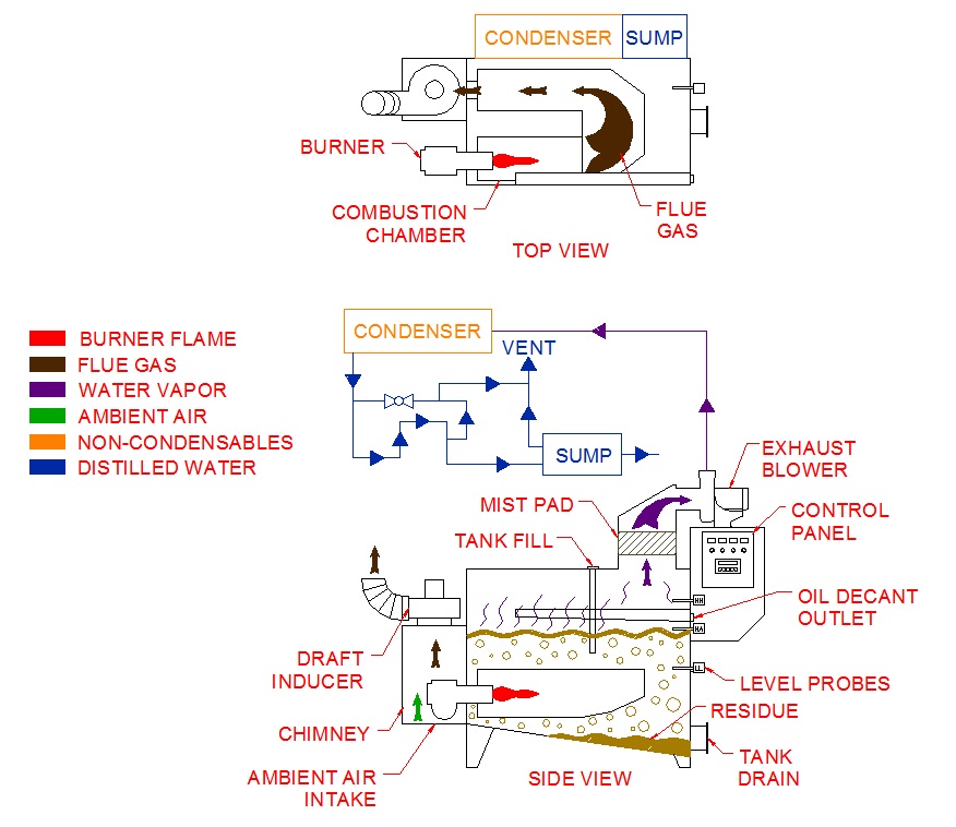
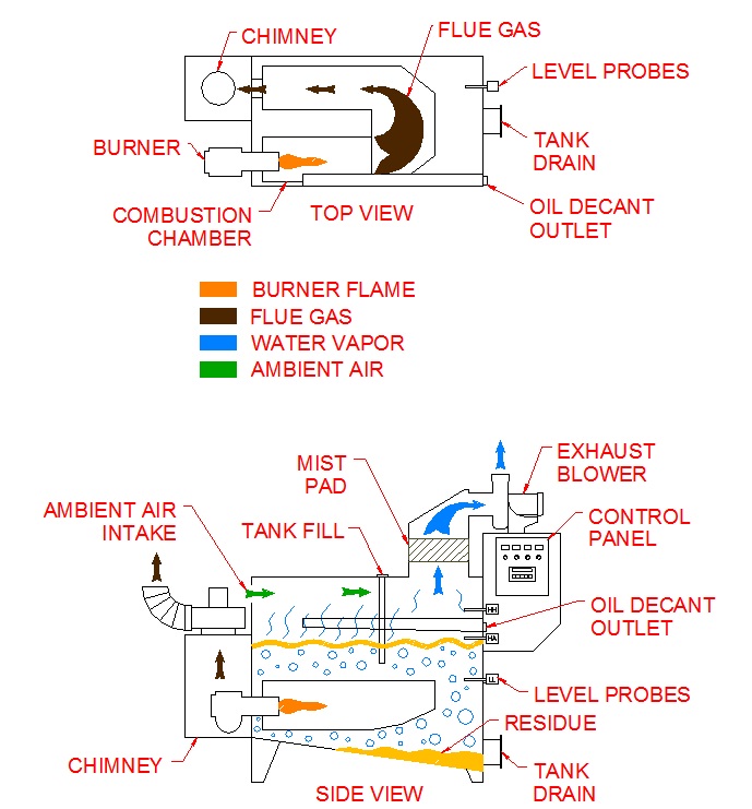
- Gas / Propane Flow Diagram
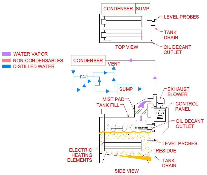
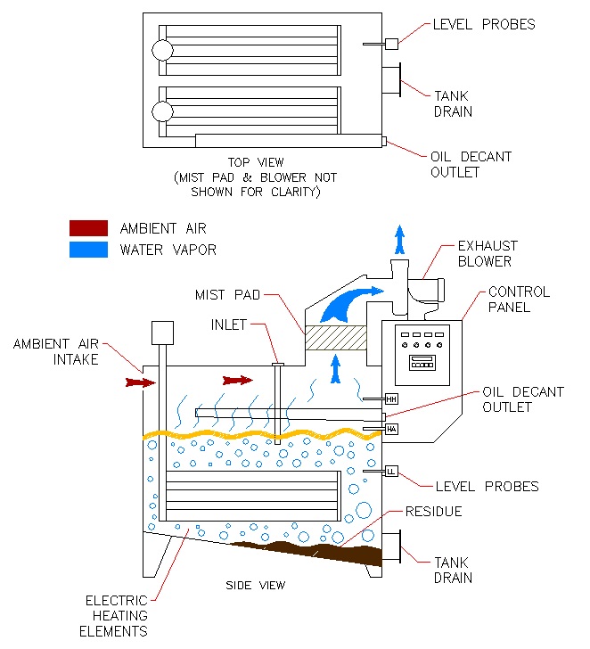
- Electric Flow Diagram
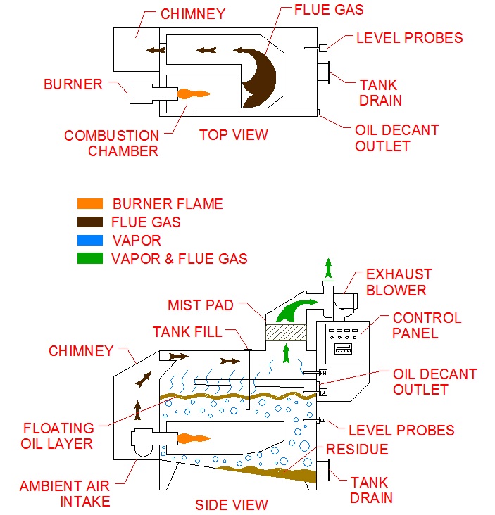
- Oil / Diesel / Kerosene Flow Diagram
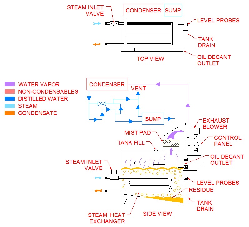
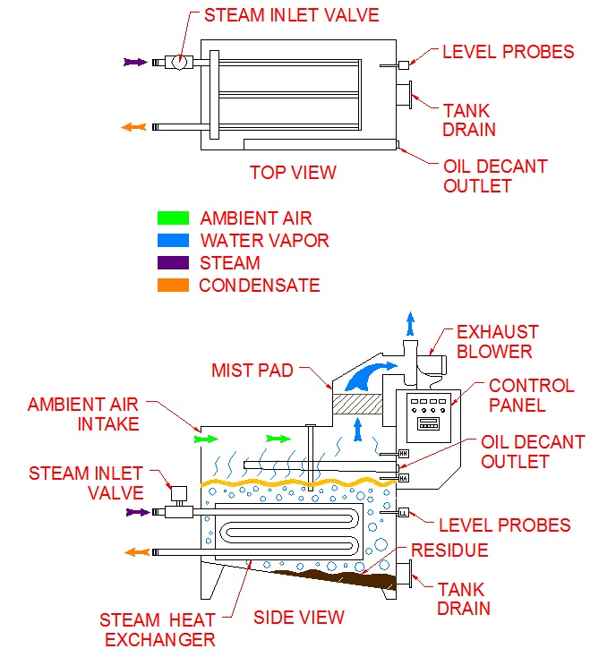
- Steam Flow Diagram
Distillation Mode Only
- The hot water vapor created inside the evaporator is drawn through the mist eliminator by the exhaust blower and pushed through the shell and tube condenser. The water vapor is condensed and then captured as high quality distilled water in the sump located directly below the condenser support shelf.
- The dehumidified air passes through another mist eliminator and is returned for recirculation through the evaporator tank.
- Distillation Flow Diagram With Gas/Propane/Oil Heat Source
- Distillation Flow Diagram With Steam Heat Source
- Distillation Flow Diagram With Electric Heat Source