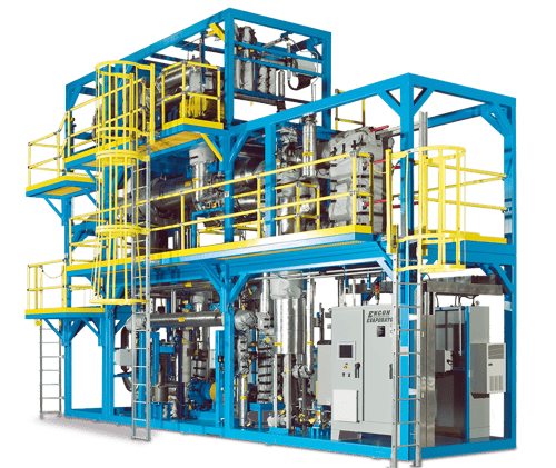
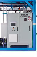
Mechanical Vapor Recompression (MVR) Evaporator
Slash wastewater disposal costs by up to 95% with the powerful ENCON MVC Evaporator.


Hauling is Costly
Industrial and commercial facilities that generate wastewater spend too much money paying for hauling & disposal of waste streams that are mostly comprised of water.
MVR Evaporation is Cost Effective
ENCON MVR Evaporators are ultra-efficient with a typical operating cost of $0.01-$0.02 per gallon.


Advantages of ENCON MVR Evaporators
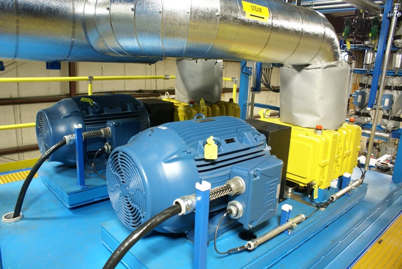
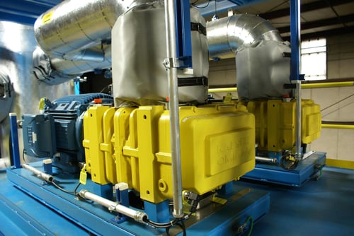
Blower(s) are used on ENCON MVR Evaporators to compress the water vapor for the purpose of raising its pressure and saturation temperature. This produces the desired heat transfer in the main heat exchanger for recycling the energy in the vapor, which greatly improves energy efficiency.
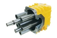
A rotary lobe or centrifuge blower may be used, depending on the application and the size of the unit. For smaller units, a rotary lobe blower may be utilized. In a rotary blower, also known as a roots blower, two rotary pistons rotate in opposite directions. In larger units, centrifugal fans are often used. These are continuous flow machines which have a spiral type housing and a rotating impeller.
Features:
High Alloy Rotary Lobe Vapor Compressors
- Analog temperature monitoring of oil for over temperature protection of blower
Duplex Stainless Steel Centrifugal Vapor Compressors
- Corrosion resistant materials of construction
- Vibration monitoring
- Bearing temperature monitoring
- Forced oil lubrication system
- Lubrication oil flow meters
- Casing temperature monitoring
ENCON MVR systems comes standard with Allen-Bradley controls. The ENCON system is fully automated from start-up all the way through to automated CIP cycles.
Automation includes: wastewater feed, automatic discharge of concentrated residue from the Separation Tank, automatic transfer of distillate from the distillate sump, and automatic cleaning (Clean-in-Place) of heat exchangers. Numerous variables such as temperature, pressure, and water level are monitored continuously, and will trigger various alarm conditions that notify the operator of deviation from normal operating mode.
Features
- PLC: Allen-Bradley Compact Logix – standard
- HMI: Allen-Bradley Panelview Plus 6 1250, 12.1”
- Touch screen interface is standard
- Fully automated
- Automated % volume reduction/ residue concentration control based on boiling point elevation
- Automated Clean-In-Place (CIP)
- Automated system dump
- Interlocks and enable status built in as popup screens to aid operator with troubleshooting
- Trend screens and data logging of process variables
- Alarm data logging – time stamped and archived
- Help screens built into HMI in both operating and alarm screens
- Electrical schematic built into HMI screen
- Evaporator owner’s manual built into HMI screen
- Optional chemical additions (such as anti-scalant or anti-foam) automated for ppm control by pacing the flow to feed rate
Four Step Mist-Elimination Process
- Vaned process vessel inlet device to minimize droplet formation and dissipate force into the separation tank.
- Vessel diameter carefully designed for optimal droplet disengagement.
- Chevron vane pack mist eliminator (alloy matches vessel) for removal of larger droplets and decreased loading on mesh mist pad.
- Mesh mist pad (alloy matches vessel) for small droplet removal
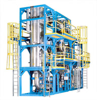
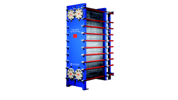
Plate and Frame Heat Exchanger:
This type of heat exchanger uses metal plates to transfer heat between two liquids. The major advantages of
this type of heat exchanger are a compact footprint and that the fluids are exposed to a much larger surface area because the fluid spread out over the plates, which facilitates the quick transfer of heat.
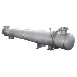
Shell and Tube Heat Exchanger:
As the name implies, this type of heat exchanger consists of a shell with a bundle of tubes inside. One fluid runs through the tubes and other fluid flows over the tubes to transfer heat between the fluids. This type of heat exchanger has a larger footprint than a plate & frame heat exchanger, but has the advantage of being much more resistant to scaling and fouling.
ENCON uses the highest quality, brand name industrial components on all our MVR Evaporators. One of the easiest ways to save on manufacturing costs is to use lower quality, commercial grade components. This allows a vendor to save a little money upfront without a customer knowing, but it comes at the cost of long term durability.
While ENCON always strives to provide the most value for our customer's dollar, we reject using inferior components to try and save a few dollars. We view our customers as long term partners and we want them to be as delighted with our products ten years down the road as they are the first year. With names like Rosemount, Gould, Sulzer, Ashcroft and Endress Hauser, you can be assured that all the components on the MVR Evaporator are the very best.
ANSI/API Centrifugal Pumps - feed and recirc.
- Typical is Gould's 3196 XLTi or Sulzer CPT
- Double Mechanical Seals
- Seal pot system for mechanical seals
- Open Impellor for handling solids
- Bearing case separated from liquid end of pump
- Motor separated from bearing (long shaft design)
Electric Motor Protection – Blower(s) and Recirc Pump
- Over temperature protection on motor windings
- Aegis grounding rings on bearings
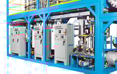
Electrical Panels
- UL/CUL Rated
- SSCR rating of 65,000 amps (typical)
ANSI/API Centrifugal Pumps - feed and recirc.
- Typical is Gould's 3196 XLTi or Sulzer CPT
- Double Mechanical Seals
 Seal pot system for mechanical seals
- Open Impellor for handling solids
- Bearing case separated from liquid end of pump
- Motor separated from bearing (long shaft design)
Electric Motor Protection – Blower(s) and Recirc Pump
- Over temperature protection on motor windings
- Aegis grounding rings on bearings
Electrical Panels
- UL/CUL Rated
- SSCR rating of 65,000 amps (typical)
Measurement sensors
 Rosemount - magnetic flow meters
- Micro Motion - Coriolis mass flow meter
- Badger - Ultrasonic flow meter
- Rosemount RTD temperature sensors and transmitters
- Rosemount Pressure transmitters
- Ashcroft Pressure gauges
- Rosemount Guided Wave Radar Level Probes
- Endress Hauser - Level switches
Process vessels designed to meet ASME Section VIII pressure vessel codes with mechanical safeties (rupture disks)
Valves
 2 Piece AVCO valves with re-enforced teflonseats
- Spring return actuators for fail safe return to safe position
- 2 position limit switches on skid boundary valves
- Analog control valves
- Low point and isolation valves
- Low point drains included in design
- Check valves to prevent back flow
- Festo air solenoid valves with Ethernet/IP control
- 3 way valves on air system to safely depressurize/de-energize system automatically
Piping
 Expansion joints used to eliminate pipe stresses on piping and components such as pumps, HX, and vapor compressors. Standard material of construction is EPDM - other materials of construction are available.
- Industrial pipe supports
- Fluid and vapor velocities optimized for client waste water conditions
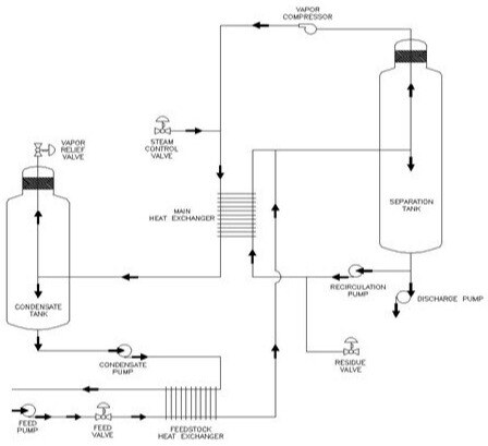
Process Description
The ENCON Mechanical Vapor Recompression (MVR) evaporation process involves our forced circulation flash evaporator utilizing mechanical vapor recompression. By using this design, the ENCON MVR Evaporator allows for minimal scaling, maximum uptime, and low operating costs.
Full Range of Upgrades, Accessories and Services to Unlock Your Evaporator’s Full Potential
ENCON offers a full range of upgrades, accessories and services to minimize labor and maximize return on investment.
Work with our consultative Sales Engineers to spec a turn-key system
Material of construction upgrades for corrosive waste streams
Automated chemical clean in place (CIP) systems
Service contracts
Free Application Feasibility Report
The centerpiece of our consultative approach is our complimentary bench scale analysis of your waste or process stream. This free analysis determines:
- How appropriate the stream is for evaporation
- Estimated reduction percentage
- Recommended materials of construction
- Recommended operating procedures.