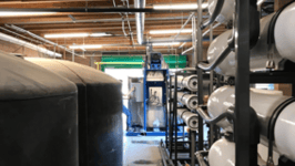
We provide turn-key integrated systems for water & wastewater treatment, minimization, reuse, or disposal.
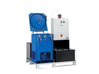
A key principle of ENCON’s consultative approach is our ability and willingness to advise when an evaporator is not the optimal solution. In these cases, we may recommend augmenting an evaporator with upstream or downstream treatment, or recommend an alternate technology. Some of our water & wastewater treatment solutions include: filtration/separation systems, reverse osmosis treatment, zero liquid discharge systems, pH adjustment, oil/water separation, and centrfuge systems.
Consult with an ENCON Sales Engineer today to discuss your application and develop the optimal wastewater treatment solution for your facility.