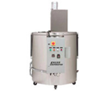
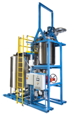
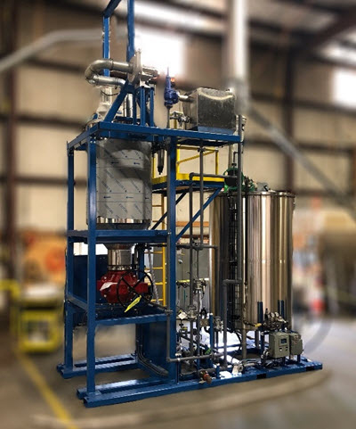
Evaporation technology offers the simplest and most effective approach to industrial wastewater minimization. ENCON is a leading Wastewater Evaporator Manufacturer, offering Evaporators and Dryers that are able to handle a wide range of waste streams simultaneously. This wastewater evaporation technology is a great option for manufacturing processes that may expand or change in the future. Many companies that generate industrial wastewater are hauling their water for disposal at a high cost per gallon. Other companies are treating the wastewater, often with labor and chemical intensive processes, and are having to adhere to increasingly strict discharge limits to their local sewer authority.
All ENCON evaporation systems are designed to operate off shift and unattended to minimize manpower requirements and cost. ENCON Sales Engineers will work with you to qualify applications based on ENCON lab and pilot scale testing. The ENCON approach is consultative with special focus on providing solutions with financial justification and regulatory compliance.
Please navigate our web site to learn more about ENCON Wastewater Evaporator systems, solutions, and lifetime support or contact ENCON directly by calling 603-624-5110 or emailing to sales@evaporator.com
read more